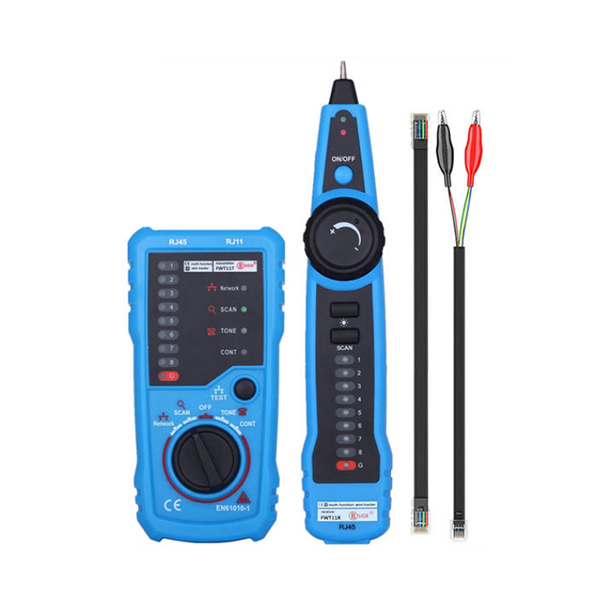
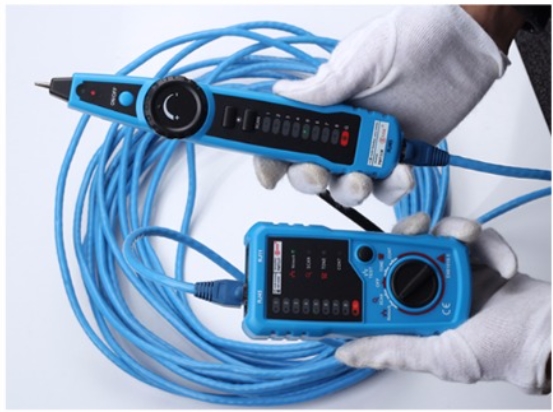
Description: FWT11 Network Cable Tester is a multi-functional handheld cable testing tool. It has wide application with reinforced cable types and multiple functions. It is a necessary testing tool for telecommunication engineering, wiring engineering and network maintenance person.
Features:
Work perfect when RJ11 or RJ45 cable is on power
Wire tracing trace RJ11, RJ45, cables or other metal wire (via adapter)
Easy and fast to locate the breakpoint without opening the wire’s cover
Network cable collation: judge short-circuit, breaking circuit, open circuit and crossing
Test line level, positive and negative polarity
Status of telephone line checking: test the working status of telephone line (idle, ringing, and off-hook) and judge TIP and RING line
Check wire continuity
Specification:
Altitude
<2000m
Anti Explosion Rating
IP40
Distance of Emitting Signal
300m
Safety Class
IEC61010-1 600V CAT III, pollution class II
Color
Black + blue
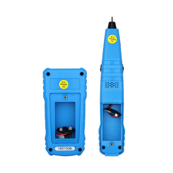
Power Supply
2*9V 6F22 batteries (Batteries are not included in the packing)
Size
Emitter: 12.6*6.4*3cm; Receiver: 20.5*4*3cm
Packing Size
22.4*11.3*4cm
Gross Weight
331g
Certificate
CE
Working Temperature
0°C to 40°C
Storage Temperature
-10°C to 50°C
Relative Humidity
80% (non-condesing)
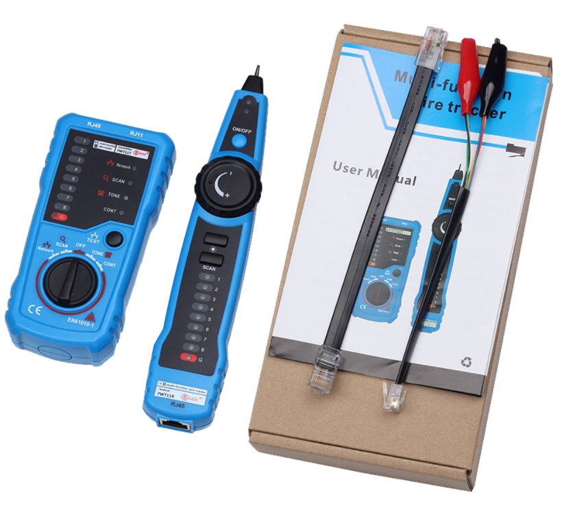
Standard Accessory:
Item
Name
Quantity
1
FWT11 Transmitter
1pc
2
FWT11 Receiver
1pc
3
Clip Adapter Cable
1pc
4
RJ45 Adapter Cable
1pc
5
User Manual
1pc
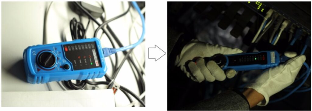
Operation Method: 1. Wire Tracking:
This function is capable of quickly finding the required line pairs among numerous ones. It is adaptable to network cable RJ45 terminal, telephone line RJ11 terminal. Via an adapter can test other metal wires.
Turn the emitter’s function rotary knob to SCAN position
Connect one end of tested line to the corresponding terminal of emitter (e.g. RJ45, RJ11) or connect to RJ11 terminal via an adapter
SCAN indication light on means emitter starts to send signal to tested wire.
Power on the receiver, hold receiver and press “SCAN”button to test the other end of tested line (e.g. near line stacking of telephone line distribution cabinet, terminal box, hub, and exchanger). Compare the sound sent by receiver, the line with the loudest sound close to probe will be the target.
Adjust the volume of receiver by pressing the volume rotary knob during test to adapt to site environment.
Note: You can connect headset to the headset jack of receiver in places with loud noise.
2. Network Cable Collation
It tests physical connection status of network cable, such as open circuit, short connection, miswire and reverse connection.
Turn the emitter’s function’s rotary knob to Network position
Connect one end of network cable to RJ45 socket of emitter, and connect another end of network cable to RJ45 socket of receiver
Press “TEST”button to start test. Line pair indicator lights will tell results
Short connection: there will be 2 or more lights on simultaneously on the receiver. The lighting quantity indications the quantity of shorted wires.
Open circuit: on the receiver, the corresponding line pair indicator light will not turn on.
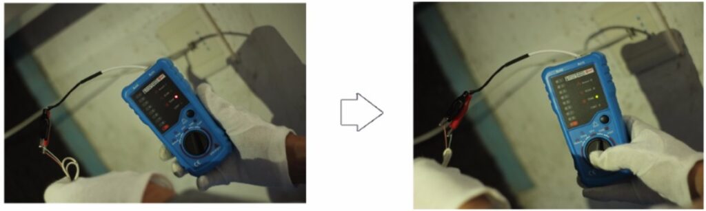
3. Test line level, positive or negative polarity:
User the emitter to test DC level, positive or negative polarity in circuits.
Transmitter to the rotary knob to telephone stalls, the transmitter began to work.
Connect RJ11 crystal head terminal of adapter to RJ11 terminal of emitter. Clamp the tested line with a red-black clip.
If telephone line status indicator light turns red (in the middle of button switch), The red end is positive, and the black end is negative. If it turns green, the red end is negative and black end is positive.
The light is brighter when level is higher. The light dims when level is lower.
4. Status of Telephone Line Test Use the emitter only to test the status of working telephone lines.
Operation method to judge TIP or RING line:
Turn the emitter’s function rotary knob to TONE position
Connect RJ11 crystal head terminal of adaptor to RJ11 terminal of emitter. Clamp the tested line with a red-black clip.
If telephone line status indicator light is red, the red end is TIP line, and the black end is RING line. If it is green, the red end is RING line and black end is TIP line.
Line level judging: the higher is the level, the higher is the level; The dimmer is the light, the lower is the level.
Operation method to judge whether the telephone line is idle, ringing or off-hook:
Turn the emitter’s function rotary knob to TONE position
Connect RJ11 crystal head terminal of adaptor to RJ11 terminal of emitter. Clamp the red clip to RING line and black clip to TIP line.
If telephone line status indicator light is green, it means line is idle; Light off means off-hook; If it is green or red and flashes regularly; it means the telephone line is in ringing.
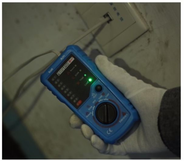
5. Continuity checking
Turn the emitter’s function rotary knob to CONT position
Connect RJ11 crystal head terminal of adaptor to RJ11 terminal of emitter. Clamp the red and black clip to the two ends of the tested wire.
“CONT”light on means the wire is continuous. Less line impedance, the brighter is the light.
6. Low Battery Capacity Indication Emitter low battery capacity indication: When battery of emitter is lower than working voltage, the power light will flash. It’s time to replace the battery.
Receiver low battery capacity indication: There is a luminous diode on receiver probe, which becomes dim when voltage is low. When the indicator light is very dim, set the emitter to wire scanning and working status, approach RJ45 terminal of emitter with receiver probe, and adjust the volume of receiver till maximum. If there is no sound or very low sound sent by receiver, it’s tie to replace the battery.