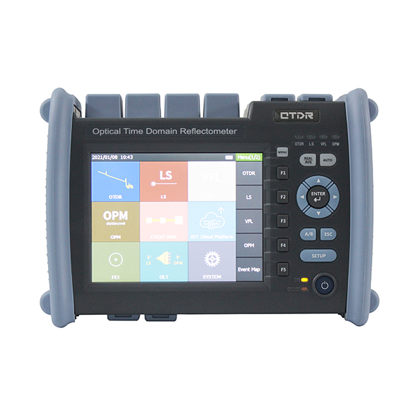
Optical Time Domain Reflectometer, OTDR for short, is an electronic-optical instrument that is used to characterize optical fibers. It locates defects and faults, and determines the amount of signal loss at any point in an optical fiber. The OTDR only needs to have access to one end of a fiber to make its measurements. An OTDR takes thousands of measurements along a fiber. The measurement data point spacing is as low as 5 cm (2 inch). The data points are displayed on the screen as a line sloping down from left to right, with distance along the horizontal scale and signal level on the vertical scale. By selecting any two data points with movable cursors, you can read the distance and relative signal levels between them.
How to use Optical Power Meter and Optical Light Source
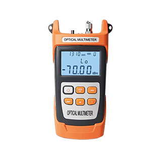
Optical Power Meter (OPM) is a device used to measure the optical power in an optical signal. The term usually refers to a device for testing average power in fiber optic systems.
Optical Light Source (OLS) is an apparatus that uses a diode laser or LED as a stabilized light emitter. It is used with Optical Power Meter that measures the power received, determining the attenuation of the optical fiber segment.
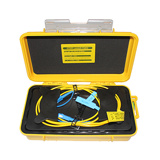
OTDR Launch Cable is also named like OTDR Launch Lead, or OTDR Launch Reel, or OTDR Launch Fiber, or pulse suppressor, or OTDR Fiber Ring.
OTDR Launch Cable is used to connect OTDR and fiber under test to measure the insertion loss of the near-end connection of fiber optic network. It is necessary when using OTDR to measure complete link loss of optical fiber. It reveals the insertion loss and reflectance of the near-end connection of optical fibers.
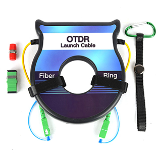
OTDR Fiber Ring is also named like OTDR Launch Lead, or OTDR Launch Reel, or OTDR Launch Fiber, or pulse suppressor, or OTDR Fiber Ring.
OTDR Fiber Ring is used to connect OTDR and fiber under test to measure the insertion loss of the near-end connection of fiber optic network. It is necessary when using OTDR to measure complete link loss of optical fiber. It reveals the insertion loss and reflectance of the near-end connection of optical fibers.
OTDR is widely used in fiber optic network, from fiber installation to maintenance, to fault locating, to repair, etc.
OTDR is used to: 1. Measure fiber loss (attenuation) for fiber optic network commissioning and acceptance 2. Inspect and verify incoming acceptance of fiber optic cables 3. Measure splice loss of both fiber splicing and fiber connector coupling during optical fiber installation, construction and maintenance. 4. Measure optical return loss of fiber connectors for CATV network, which should be known for signal improvement.
OTDR uses Rayleigh Scattering and Fresnel Reflection to measure optical fiber. OTDR displays a trace/curve of the fiber length and reflected light level by sending a pulse of light (Optical) into optical fiber and measuring the time (Time Domain) and strength of its reflection (Reflectometer) from Particles inside optical fiber. The curve can be analyzed on the OTDR display, or saved to computer for later analysis and comparison, or printed out. Engineers can locate fiber end, loss of fiber connector coupling, location and loss of fiber splices, the total loss of optical fiber.
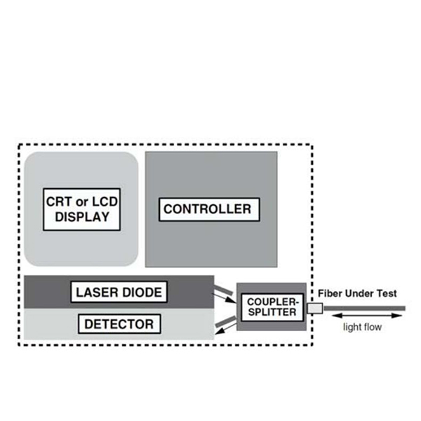
OTDR consists of a laser Diode, an Optical Sensor (APD), a Coupler/Splitter (or Circulator), a Controller, and a Display.
Laser Diode:
On Command from the Controller, Laser Diode sends out light pulses. For different measuring distance and conditions (with or without fiber splitters for example), different pulse widths can be selected. The light goes through Coupler/Splitter (or Circulator) and then into the Fiber Under Test.
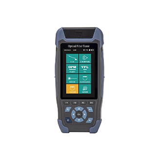
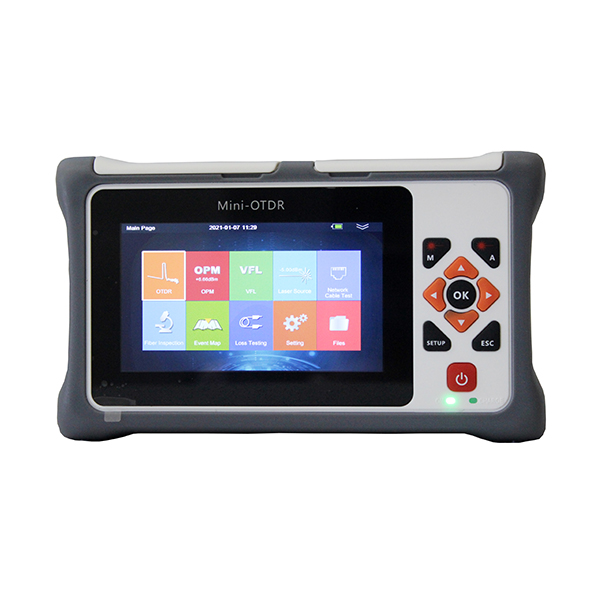
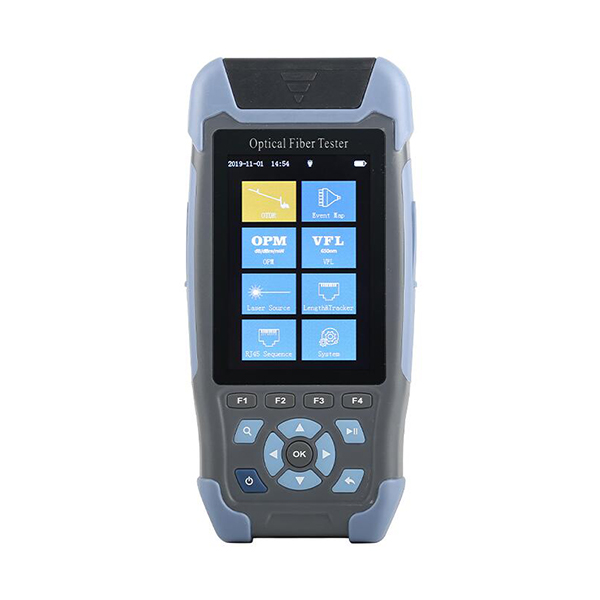
NK3200D Mini Pro Series Optical Time Domain Reflectometer adopts 3.5 inch color display screen. The UI operation interface is simple and easy to operate. It integrates OTDR, Stable Light Source, Optical Power Meter, Visual Fault Location, Cable Sequence, Cable Length, Cable Tracker and Flashlight. It adopts intelligient power saving management, 12 hours of super long measurement time to ensure the field test and maintenance work efficiently.
NK3200D are used to measure the length, loss, connection quality and other parameters of all kinds of optical fiber and cable. When there is optical signal in the line, it can still be used. The maximum test power with light is -5dBm. It can be widely used in engineering construction, link maintenance test and emergency repair of communication system of optical fiber communication system.