MAY120 MPO Optical Power Meter & MAY122 MPO Optical Light Source
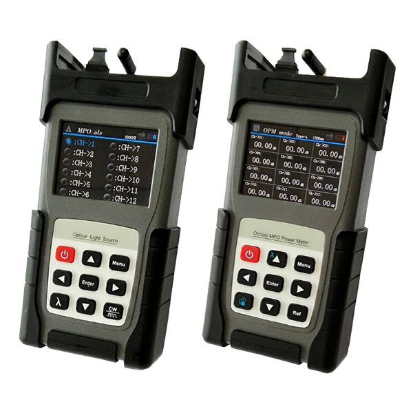
MAY120 MPO Optical Power Meter &
MAY122 MPO Optical Light Source
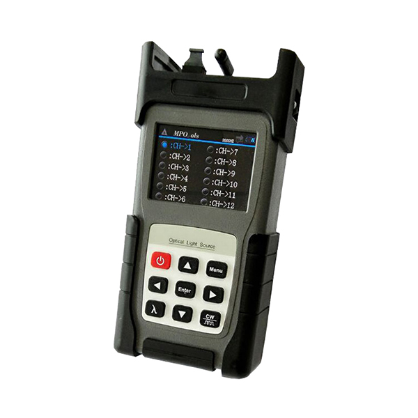
MAY122 MPO Optical Light Source
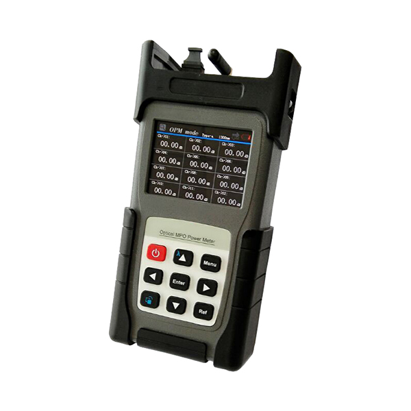
MAY120 MPO Optical Power Meter
Description:
MPO Optical Power Meter and MPO Optical Light Source are special testers developed for the current MPO cable detection. In recent years, with the rapid development of data centers and cloud computing, the demand for “multi-fiber push” (MPO) cables has also shown rapid growth. However, in test process, the traditional single-channel optical power meter test is time-consuming and the accuracy is not very good. To solve the problem, MPO series products are developed. This product can test insertion loss, polarity and other information of MPO cables with one key operation, and integrates a variety of data storage, threshold analysis and other application functions. Testing efficiency is 10 times better than traditional type. It is a good choice for field applications such as MPO testing, production line verification, and polarity determination.
Features:
- 12channels (24 channels can be customized)
- High resolutionand colorful display
- 100 data records
- If five minutes no-operation,the screen will automatically adjust backlight and enters energy-saving mode
- One key switching of four function interfaces (single-channel power, 12-channel power meter MPO line sequence test, histogram interface)
- USB interface can be used to directly copy data to the computer
- Users can customize the threshold for testing
- Built-in 3500mAh large-capacity lithium battery that can be used more than 10 hours
- User-friendly – Computer interaction interface and easy to operate
| MAY120 MPO Optical Power Meter: | |
| Detector | InGaAs |
| Wavelength Range | 850~1700nm |
| Calibration Wavelength | 850/1300nm or 1310/1550nm |
| Measuring Range | +3~-50 dBm |
| Scan Speed | <0.2s/channel |
| Resolution | 0.01dB |
| Insertion Loss Accuracy | ±0.1dB |
| Channel | 12 (24 can be customized) |
| Linearity | ±0.2dB (+5~-50dBm) |
| Communication | USB |
| Interface Type | SM or MM, 12 or 24 cores female MPO/PC connector |
| Dimension | 205*115*55mm |
| Weight | 0.85kg |
| MAY122 MPO Optical Light Source: | |
| Detector | FP LD |
| Wavelength | 850nm or 1300nm or 1310nm or 1550nm |
| Frequency | 0Hz, 270Hz, 1KHz, 2KHz |
| Fiber type | 9/125um or 50/125um or 62.5/125um |
| Interface Type | SM or MM, 12 or 24 cores female MPO/PC connector |
| Output Power | >-10dBm |
| Stability | ±0.2 (15min.) , ±0.5 (8hours) |
| Dimension | 205*115*55mm |
| Weight | 0.85kg |
| Item | Name | Quantity |
| 1 | MPO Optical Power Meter & MPO Optical Light Source | 1 set |
| 2 | 12V Power Adapter | 1pc |
| 3 | User Manual | 1pc |
| 4 | Certificate | 1pc |
Product Highlights:
MPO Optical Power Meter:
1. Automatic scanning and testing all fibers in MPO connectors.
Built-in polarity identification support testing polarity of MPO cables.
Troubleshoot a single fiber within an MPO trunk and provide result.
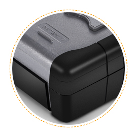
2. Shatter-Resistant Rubber Shell:
Protect the power meter from falling, shocking and wearing.
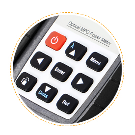
3. Scientific Button Design:
Easily achieve multi-function only by a single button
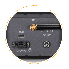
4. On-Board MPO Connector
Eliminates the use of costly fan-out cords to test MPO fibers.
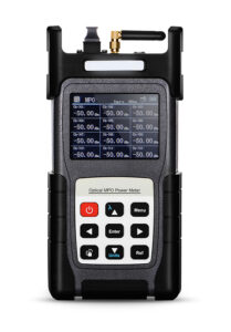
5. High Precision of Colored LCD display:
Automatically test and display of all fibers in MPO connectors
6. Store Up to 100 Records of Test Results
Datas can be uploaded to a PC through a USB interface
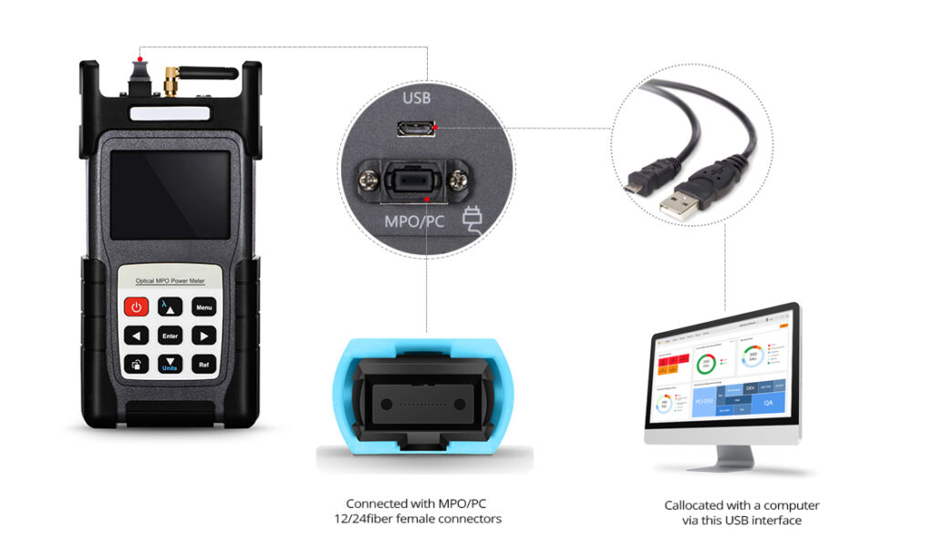
7. On the Importance of Real Test
Support both multimode and single mode MPO trunk fiber test
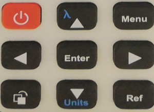
Button Description:
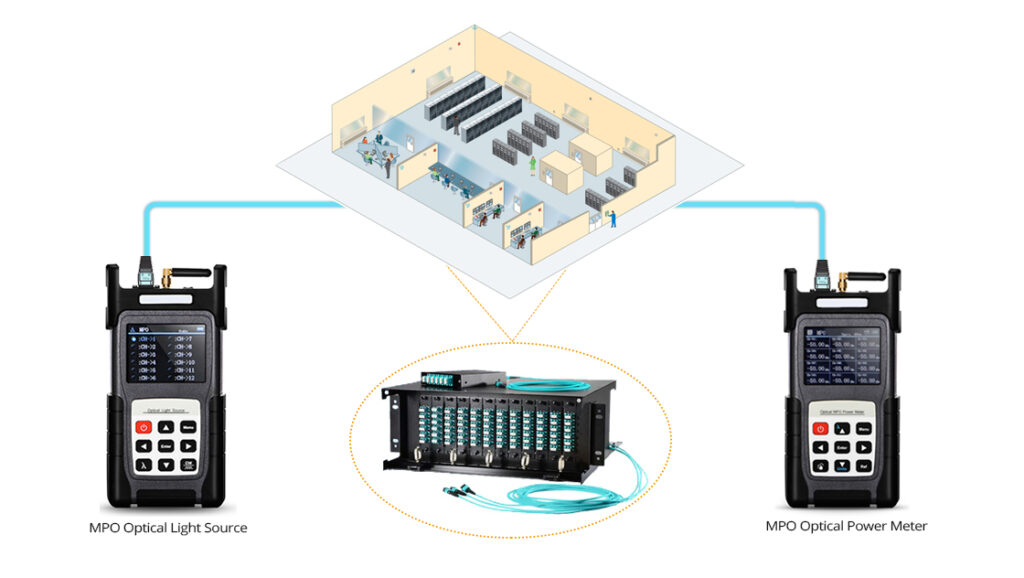
MPO Optical Power Meter provides 12-channel optical power measurement, single channel & multi channel power display. The calibration wavelength is the most commonly used wavelength in the field of optical communications: 850nm, 1300nm, 1310nm, and 1550nm. MPO Optical Light Source is a 12-channel light source and the wavelength that can be customized. It outputs through MPO adapter and is mainly used with MPO Optical Power Meter.
When used alone, it can provide a single-wavelength conventional light source.
MPO Optical Power Meter and MPO Optical Light Source can be used together to test the loss and polarity of the MPO jumper/patchcord. The threshold setting helps quickly determine whether the MPO jumper loss is excessive.
Button function
| Key (from Left to Right) | Function |
| Power | Turn on and off |
| Wavelength | Wavelength switching and multiplexing |
| Menu | Menu operation, set work in MPO mode or OPM mode. Threshold setting, pairing and viewing history |
| Left Button | Move the cursor to left |
| Confirmation | Data can be saved in MPO mode, and enter the selected function in the normal mode |
| Right Button | Move the cursor to right |
| Display | Function switching shortcuts, switch line sequence testing, single-channel power meter, multi-channel power meter, and histogram interface |
| Unit | Switching Units, and Down Button |
| Reference | reference value |
Operation Instructions:
1. Pairing:
MPO Tester must be paired before using.
MPO testers all are paired, if there are multiple sets of instruments and in the case of simultaneous use, it can be confused. At this time, suggest to re-pair that can help to use normally. The specific matching steps are as follows:
After booting, press Menu to enter the main menu, press up or down to select pairing mode, and press Enter to enter pairing mode, as shown in Figure 1-1.
Start → Menu to enter the main menu → up and down keys to search light source, press Enter to enter the pairing mode→ If you find the light source,then it will display the corresponding unique ID, as shown in Figure 1-1, press the Enter key to save the paired MPO light source address.
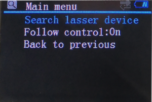
Figure 1-1
Pairing Interface
2. MPO mode:
Insertion loss test: Press Menu button to enter the main menu as shown in Figure 2-1:
Up and down button select mode selection Press Enter key to enter, select MPO mode, press Enter to confirm, then select line sequence selection, select the type to be tested after entry (e.g.: A-Type), and switch up and down keys to select the threshold setting, up, down, left, and right keys could adjust the threshold, as shown in Figure 2-2.
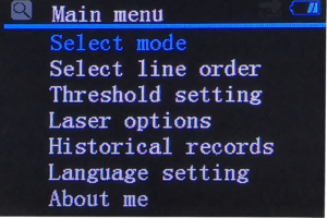
Figure 2-1: Main Menu
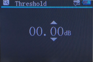
Figure 2-2: Threshold Settings
3. OPM Mode:
There are two main functions in this mode, multi-channel power meter (Figure 3-1) and single-channel power (Figure 3-2).
Multi-channel power meter: Equivalent to a 12-channel optical power meter that supports single channel or all channel selection and release. When selected, it can edit one channel wavelengths. When selected all channels,then all channels can be operated together.
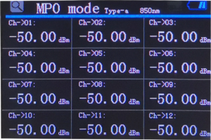
Figure 3-1: Multi-channel power meter
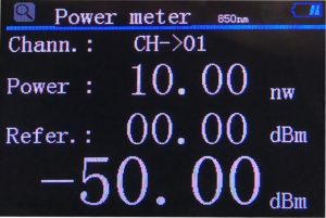
Figure 3-2: Single Channel Power Meter
| MPO Channel | 12: 12 channel
24: 24 channel |
| Fiber Type | 9: 9/125um
5: 50/125um 6: 62.5/125um |
| Wavelength | 850: 850nm
1300: 1300nm 1310: 1310nm 1550: 1550nm |
