PLC Splitter Inspection Standard
1. Scope
The standard stimulates the package, working environment, service life, material, function and performance, and label, packing, transportation and storage of optical splitter.
This standard is applicable for series of passive optical splitters for access network.
2. Cited documents
GB/T 5169.7-2001 Fire hazard testing for electric and electronic products Test methods Diffusion type and premixed type flame test methods
SJ/T 11364-2006 Marking for control of pollution caused by electronic information products
YD/T 979-2009 Specifications and Test Methods for Optical Fiber Ribbon
YD/T 1117-2001 Specification of all Optical Fiber Branching Devices
YD/T 1272.1-2003 Optical fiber connector Part I: type LC
YD/T 1272.3-2005 Optical fiber connector Part I: type SC
YD/T 1272.4-2007 Optical fiber connector Part I: type FC
YD/T 2000.1-2009 Integrated optical path devices based on planar lightwave circuit Part 1: Optical power splitter based on PLC technology
ITU-T G.657 Characteristics of a bending-loss insensitive single-mode optical fibre and cable
GR-1209-CORE Generic Requirements for Passive Optical Components
GR-1221-CORE Generic Reliability Assurance Requirements for Passive Optical Components
3. Product classification
Optical fiber can be represented as M×N. M refers to input fiber number and N output fiber number. In FTTx system, M can be 1 or 2 and N can be 2, 4, 8, 16, 32, 64, and 128.
Optical splitter can be in equal or non-equal splitting ratio. This standard emphasizes on equal splitting ratio.
Based on manufacturing technologies, optical splitters can be FBT coupler and PLC Splitter. According to the application, optical splitter with equal splitting ratio applies PLC technology and optical splitter with non-equal splitting ratio applies PLC or FBT technology.
4. Product Specification
Manufacturing technology, splitting ratio, package, connectorization type, connector type, fiber diameter, input fiber length and output fiber length
4.1. Manufacturing technology
| Code | P | F |
| Manufacturing technology | PLC | FBT |
4.2. Splitting ratio
| Code | 1002 | 1004 | 1008 | 1016 | 1032 | 1064 | 1128 |
| Splitting ratio | 1×2 | 1×4 | 1×8 | 1×16 | 1×32 | 1×64 | 1×128 |
| Code | 2002 | 2004 | 2008 | 2016 | 2032 | 2064 | 2128 |
| Splitting ratio | 2×2 | 2×4 | 2×8 | 2×16 | 2×32 | 2×64 | 2×128 |
4.3. Package
| Code | B | R | M | T | P |
| Package | Plastic box | Rack | Blockless | Tray | Insertion module |
4.4. Connectorization type
| Code | F | N | A |
| Connectorization type | Pigtail with connector | Fiber without connector | Adapter |
4.5. Connector type
| Code | SU | FU | LU | SA | FA | LA |
| Connector type | SC/UPC | FC/UPC | LC/UPC | SC/APC | FC/APC | LC/APC |
4.6. Fiber diameter
| Code | Φ0.25 | Φ0.9 | Φ2.0 | Φ3.0 |
| Fiber diameter | 0.25mm bare fiber | 0.9mm loose tube | 2.0mm loose tube | 3.0mm loose tube |
4.7. Input fiber length
| Code | 05 | 15 | 20 | XX |
| Input fiber length | 0.5M | 1.5M | 2M | customized |
4.7. Output fiber length
| Code | 05 | 15 | 20 | XX |
| Output fiber length | 0.5M | 1.5M | 2M | customized |
5. Serial Number(SN)
5.1. Product SN includes: manufacturing time (year and month) and serial number in the manufacturing month.
S=year-month-Serial number-Package
Year: the last 2 numbers, month: 2 numbers, serial number in the manufacturing month: 6 numbers
5.2. Example:
SN:10-04-000005
It means the optical splitters were manufactured in April, 2014, and the serial number in the manufacturing month is 000005.
6. Packge requirement
PLC Splitter packages should be economic, efficient, rigid and compact. The coiled fibers inside the packages should be ensured at reasonable bending radius and not damaged. All components should be fixed well and there should be enough space for administration, maintenance, connection, installation and inspection.
This standard defines the following five packages for PLC Splitter, See Table 1:
| Table 1: Package method for PLC Splitter | |||
| Name | Package Method | Port Type | Application |
| Rack Splitter | Rack | Adapter | 19”rack |
| Blockless Splitter | Blockless | Adapter | Fiber Optic Splice Closure, Opical Splitter Box |
| Pigtail with connector | |||
| Tray Splitter | Tray | Adapter | ODF or FDH, etc. |
| Insertion module Splitter | Insertion module | Adapter | ODF, FDH, Optical Splitter Box |
6.1. Apperance and size
In order to adapt to different installation facilities and environment, different packages and sizes of PLC Splitters are applied.
6.1.1. Plastic box package
6.1.2
6.1.2.1. Plastic box PLC Splitter is with 2.0mm or 3.0mm pigtail.
6.1.2.2. The size of plastic box PLC Splitter:
-The max. size of 1/2×2/4/8/16/32 plastic box PLC Splitter is 130mm×80mm×18mm;
-The max. size of 1/2×64 plastic box PLC Splitter is 130mm×80mm×29mm;
-The max. size of 1×128 plastic box PLC Splitter 200mm×150mm×40mm
6.1.3. Rack package
Rack package PLC Splitter should provide fiber adapter, is suitable for 19” installation rack and should be used together with fiber guidance device.
The max. size of rack package is 483mm×44.5mm×260mm.
6.1.4. Blockless package
Blockless package PLC Splitter have two types: with connectors and without connectors.
6.1.4.1. Without connector:
The input and output fibers is Φ0.25mm or Φ0.9mm, the max. size is as follows:
-1/2×2/4/8/16/32/64 PLC Splitter: 70mm×12mm×6mm;
6.1.4.2. With connector:
The input and output fibers is Φ0.9mm, the max. size is as follows:
-1/2×2/4/8/16 PLC Splitter: 70mm×12mm×6mm;
-1/2×32 PLC Splitter: 80mm×20mm×6mm;
-1/2×64 PLC Splitter: 100mm×40mm×6mm
6.1.5. Tray package:
Tray package PLC Splitter should provide fiber adapter and be used together with fiber guidance device.
Apperance and size of Tray package PLC Splitter should meet the requirement of 12 Fibers Splice and Distribution Integrated Tray from《Technical Requirement for Outdoor Cabinet from China Telecom》 and《Technical Requirement for ODF from China Telecom》. It occupies the tray space as follows:
-1/2×2/4/8/16 Tray package PLC Splitter occupies the space of 1pc of 12 Fibers Splice and Distribution Integrated Tray;
-1/2×32/64 Tray package PLC Splitter occupies the space of 2pcs of 12 Fibers Splice and Distribution Integrated Trays. 1/2×64 Tray package PLC Splitter uses LC adapters.
6.1.6. Insertion module package:
Insertion module package PLC Splitter provides fiber adapters, can be installed in Optical Splitter Box, FDH, and ODF and be used together with fiber guidance device.
The basic size of Insertion module package PLC Splitter is 130mm×100mm×25mm and it occupies 1 slot. PLC Splitter with the splitting ratio of more than 16 occupies L pieces of slots (L≥2) and the size is 130mm×100mm×(26×L-2)mm. The size of PLC Splitter refer to Table 2.
| Table 2: Size of Insertion module PLC Splitter | |||
| Insertion module Types | Occupied Slots | Size (mm) (W)×(D)×(T) | |
| 1×4 Insertion module (SC) | 1 | 130×100×25 | |
| 1×8 Insertion module (SC, LC) | 1 | 130×100×25 | |
| 1×16 Insertion module (SC, LC) | 2 | 130×100×50 | |
| 1×32 Insertion module (LC) | 3 | 130×100×76 | |
| 4 | 130×100×102 | ||
| 1×32 Insertion module (SC) | 4 | 130×100×102 | |
| 1×64 Insertion module (LC) | 6 | 130×100×154 | |
| 8 | 130×100×206 | ||
| 1×64 Insertion module (SC) | 8 | 130×100×206 | |
| 1×128 Insertion module (LC) | 11 | 130×100×284 | |
The sizes of Insertion module PLC Splitter as follows:
6.1.6.1. 1×4 SC Insertion module PLC Splitter
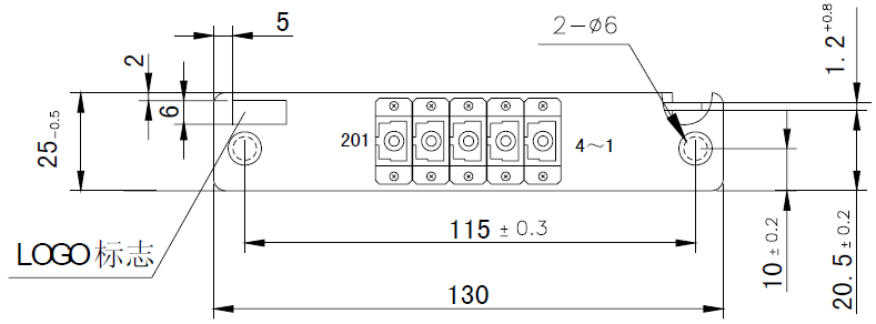
Photo 2: 1×4 SC Insertion module PLC Splitter Size (1 slot)
6.1.6.2. 1/2×8 LC Insertion module PLC Splitter
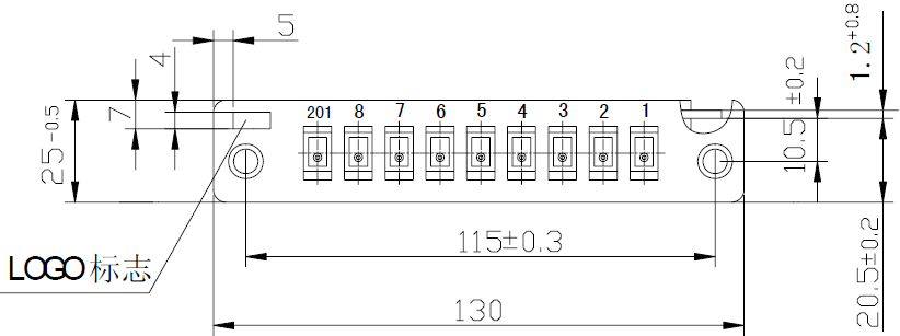
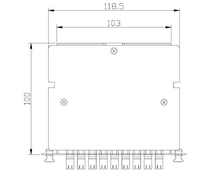
Photo 3: 1×8 LC Insertion module PLC Splitter Size (1 slot)
6.1.6.3. 1/2×8 SC Insertion module PLC Splitter
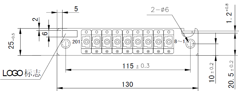
Photo 4: 1×8 SC Insertion module PLC Splitter Size (1 slot)
6.1.6.4. 1/2×16 LC Insertion module PLC Splitter
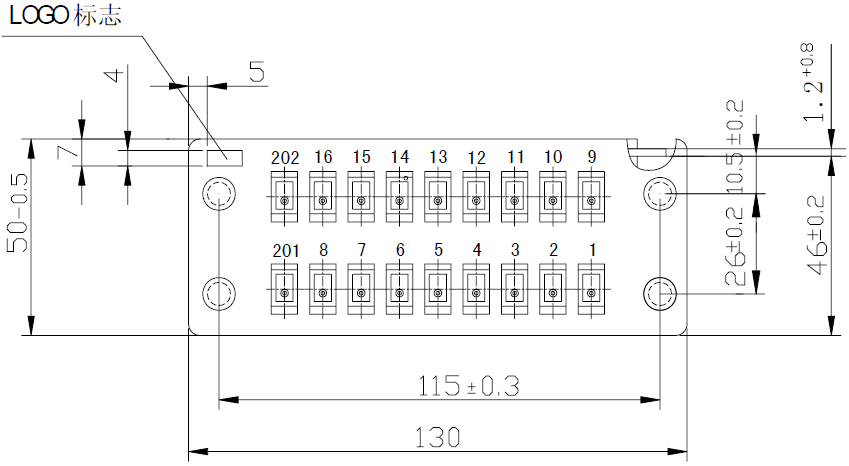
Photo 5: 1/2×16 LC Insertion module PLC Splitter Size (2 slots)
6.1.6.5. 1/2×16 SC Insertion module PLC Splitter
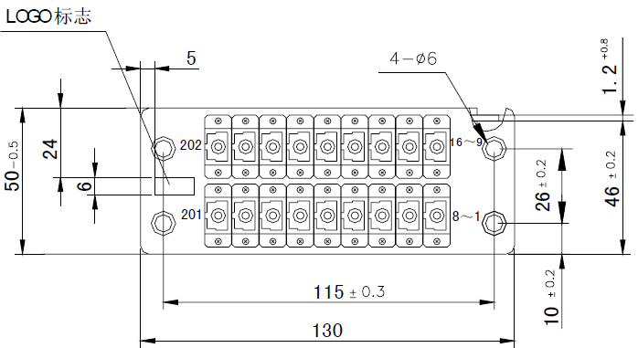
Photo 6: 1/2×16 SC Insertion module PLC Splitter Size (2 slots)
6.1.6.6. 1/2×32 LC Insertion module PLC Splitter

Photo 7: 1×32 LC Insertion module PLC Splitter Size (3 slots)
6.1.6.7. 1/2×32 SC Insertion module PLC Splitter
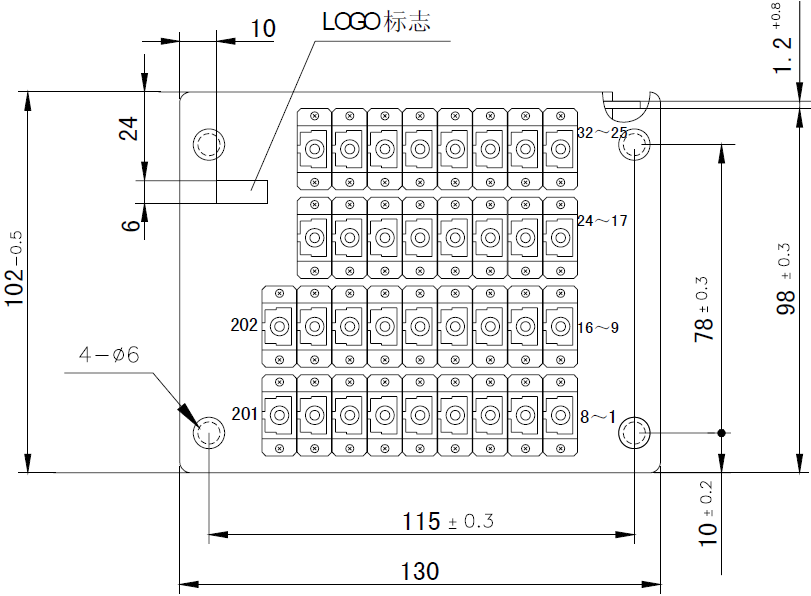
Photo 8: 1/2×32 SC Insertion module PLC Splitter Size (4 slots)
6.1.6.8. 1/2×64 LC Insertion module PLC Splitter
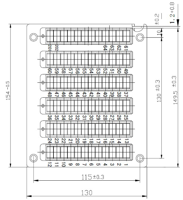
Photo 9: 1/2×64 LC Insertion module PLC Splitter Size (6 slots)
6.1.6.9. 1/2×64 SC Insertion module PLC Splitter

Photo 10: 1/2×64 SC Insertion module PLC Splitter Size (8 slots)
6.1.6.10. 1/2×128 LC Insertion module PLC Splitter
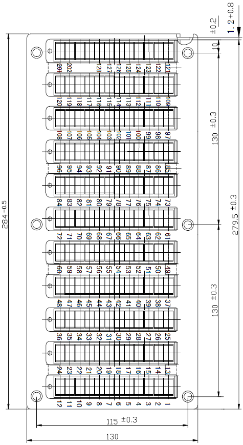
Photo 11: 1/2×128 LC Insertion module PLC Splitter Size (11 slots)
6.2. Adapter requirement
SC, FC and LC adapters for option. In order to reduce device size and save installation volume, PLC Splitter can use LC adapters.
6.2.1. Technical conditions
Adapter should meet standards of YD/T 1272.3-2005 (SC), YD/T 1272.4-2007 (FC/UPC and FC/APC), YD/T 1272.1-2003 (LC).
The connector endfaces are UPC, and APC for analog CATV signal.
6.3. Pigtail requirement
The pigtail diameter of Plastic box PLC Splitter is Φ2mm and Φ3mm, while Blockless PLC Splitter Φ0.9mm orΦ0.25mm. The fiber meets ITU-T G.657A standard.
The output fiber of PLC Splitter with Φ0.25mm fiber uses fiber ribbon, which meet YD/T 979-2009 standard. The color code of fiber ribbon meets YD/T 979-2009 in Table 2. PLC Splitter at coupling ratio of more than 8 uses groups of fiber ribbons.
| Table 2: Color code of fiber ribbon | ||||||||
| Number | 1 | 2 | 3 | 4 | 5 | 6 | 7 | 8 |
| Color Code | blue | orange | green | brown | gray | white | red | black |
7. Working enviroment and life requirement
7.1. Working temperature
PLC Splitter should work normally at -40~+85°C.
7.2. Storage temperature
PLC Splitter can be storedat -40~+85°C for a long time.
7.3. Working air pressure
PLC Splitter can work normally at air pressure of 106Kp.
7.4. Working humidity
PLC Splitter can work normally at relative humidity of less than 95%.
7.5. Working life
The expected working life of PLC Splitter is no less than 25 years.
8. Material requirement
All the parts of PLC Splitters can be corrosion resistant. If the material is not corrosive, it should be made corrosive treatment. Its physical and mechanical performance should be stable and compatible with relative connection material, like cable jacket and pigtail jacket. In order to prevent corrosion and other damage, these materials should be compatible with common material in other device.
If PLC Splitters use engineering plastics, its flame retardant performance complies with the requirement of Test A in GB/T 5169.7-2001 standard.
9. Performance and requirement
9.1. Working wavelength requirement
Considering PON application, besides the wavelengths of EPON/GPON, 10G PON and ODN online testing, PLC Splitter should support working wavelength of 1260nm~1650nm.
9.2. Optical performance requirement
9.2.1. PLC Splitter of equal splitting raito
PLC Splitter of equal splitting ratio within working temperature complies with optical performance in Table 3:
| Table 3 Optical performance of PLC Splitter of equal splitting ratio | Unit: dB | |||||||
| Spec | 1×2 | 1×4 | 1×8 | 1×16 | 1×32 | 1×64 | 1×128 | |
| Fiber Type | G.657.A | |||||||
| Working Wavelength | 1260nm~1650nm | |||||||
| Max. IL (dB) | ≤4.1 | ≤7.4 | ≤10.5 | ≤13.8 | ≤17.1 | ≤20.4 | ≤23.7 | |
| Loss Uniformity | ≤0.8 | ≤0.8 | ≤0.8 | ≤1.0 | ≤1.5 | ≤2.0 | ≤2.0 | |
| Loss Uniformity between Wavelengths | ≤0.8 | ≤0.8 | ≤0.8 | ≤1.0 | ≤1.0 | ≤1.0 | ≤1.2 | |
| RL (dB) | Output cut-off | ≥50 | ≥50 | ≥50 | ≥50 | ≥50 | ≥50 | ≥50 |
| Output Open | ≥18 | ≥20 | ≥22 | ≥24 | ≥28 | ≥28 | ≥30 | |
| Directivity | ≥55 | ≥55 | ≥55 | ≥55 | ≥55 | ≥55 | ≥55 | |
Remark 1: IL of PLC Splitter without connectors decreases no less than 0.2dB in the above table.
Remark 2: IL of 2xN PLC Splitter increases no less than 0.3dB in the above table.
Remark 3: IL of PLC Splitter at 1260~1300nm and 600~1650nm increases 0.3dB.
Remark 4: Testing methods of working wavelength, IL, RL and directivity refer to Chapter 6 in YD/T 1117-2001.
Remark 5: IL between wavelenths is as follows: within wavelengths of 1260~1650nm, inject optical power of output power/waelength >-22dBm/nm and full spectrum output power >6dBm for 30 minites and monitor IL Uniformity between wavelengths.
9.2.2. Optical splitter with non-equal splitting ratio
PLC Splitter of typical non-equal splitting ratio within working temperature complies with optical performance in Table 4 and other parameters meet Table 3:
| Table 4 Optical performance of optical splitter at typical non-equal splitting ratio | Unit: dB | |
| Splitting Ratio | Max. IL for Branch | Max. IL for Branch 2 |
| 90/10 | ≤0.6 | ≤11.3 |
| 80/20 | ≤1.2 | ≤7.9 |
| 70/30 | ≤1.9 | ≤6 |
| 60/40 | ≤2.7 | ≤4.7 |
| Remark 1:90/10 means 90% power for Branch 1 and 10% for Branch 2. | ||
9.3. Environmental performance
PLC Splitter should comply with environmetal performance in Table 5.
| Table 5 Environmental performance of PLC Splitter | Unit: dB | |||
| No. | Test Name | Testing Methods | Standard | |
| IL Variation | Shape Change after Testing | |||
| a | High Temperature | 85℃ (±2℃), duration: 96h, online testing | ≤0.5 | Apperance with no mechanical damage, like deformation, crack, slack. No fiber breakage, cable pulled out, fault on fiber endface or cable sealing damage, etc. |
| b | Low Temperature | -40℃ (±2℃), duration: 96h, online testing | ≤0.5 | |
| c | Humidity and High Temperature | 75℃ (±2℃), 95% (±5%)RH, duration: 96h, online testing | ≤0.5 | |
| d | Temperature Cycling | (-40℃~+85℃), one cycle duration: 8h,21 cycles, online testing | ≤0.5 | |
| e | Water Immersion | Room temperature, tap water, duration: 168h | ≤0.5 | |
| f | Slat Spray | Saline solution: 5% NaCl, 6.5| ≤0.5 |
| |
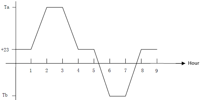
Remark 1: Temperature cycling testing changes the temperatures according to the following chart, one cycle duration: 8h, 21 cycles
9.4. Mechanical performance:
PLC Splitter should comply with mechanical performance in Table 6 and Table 3.
| Table 6 Mechanical performance of PLC Splitter | Unit: dB | |||
| No. | Test Name | Testing Methods | Standard | |
| IL Variation | Shape Change after Testing | |||
| a | Drop Test | Height: 1.8M Time: 3 axial directions, 8 times/axial direction | ≤0.5 | Apperance with no mechanical damage, like deformation, crack, slack. No fiber breakage, cable pulled out, fault on fiber endface or cable sealing damage, etc. |
| b | Vibration Test | Frequency: 10~55HZ
Sweep frequency: 45 times/minute Amplitude: 0.75mm Time: duration: 30min at X, Y, Z direction each |
≤0.5 | |
| c | Cable Torsion Test | Load::
Φ2.0mm cable: 15N Φ0.9mm cable: 4N Φ0.25mm fiber: 2N Method: Load point is 22~28cm away from the connector, ±1800 torsion, 10 times/min, 25 times |
≤0.5 | |
| d | Cable Tension Test | Load:
Φ2.0mm cable: 50N Φ0.9mm cable:4N Φ0.25mm fiber: 2N Method: Connector side: Load point is 22~28cm away from the connector, 2min Package side: Load point is 22~28cm away from the packege, 2min |
≤0.5 | |
| Remark 1: Cable Tension Test includes testings at connector side and package side. | ||||
9.5. Environmetal life
PLC Splitter should comply with environmetal life in Table 7 and Table 3.
| Table 7 Environmetal life of PLC Splitter | Unit: dB | |||
| No. | Test Name | Testing Methods | Standard | |
| IL Variation | Shape Change after Testing | |||
| a | Storage at High Temperature | Height: 1.8M 85℃ (±2℃) or highest storage temperature, humidity<40%RH, duration: 2000h | ≤0.5 | Apperance with no mechanical damage, like deformation, crack, slack. No fiber breakage, cable pulled out, fault on fiber endface or cable sealing damage, etc. |
| b | Storage at Low Temperature | Frequency: 10~55HZ
Sweep frequency: 45 times/minute Amplitude: 0.75mm Time: duration: 30min at X, Y, Z direction each |
≤0.5 | |
| c | Cable Torsion Test | (-40℃~+85℃), one cycle: 8h, 500 cycles | ≤0.5 | |
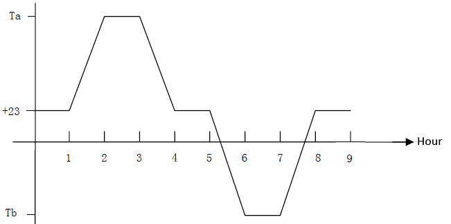
| Remark 1: Temperature cycling testing changes the temperatures according to the following chart, one cycle duration: 8h, 500 cycles | ||||
10. Mark, Packing, Transportation and Storage
10.1. Mark: PLC Splitter has permanent marks, which include the following requirements:
10.1.1. On the top of PLC Splitter, laser warning label is provided upon request.
10.1.2. Carrier’s logo and Manufacturer’s logo on PLC Splitter is provided upon requst.
10.1.3. The surface of PLC Splitter has PN and SN:
10.1.3.1. Cable marks include: manufacturer’s name, manufacturing technology, splitting ratio, package, connectorization type, connector type, fiber type, and fiber length.
10.1.3.2. Serial Number include: manufacturing time (year and month, serial number in the manufacturing month.
10.1.4. Permanent marks at ports of PLC Splitter: fiber input and output of PLC Splitter should provide permanent sequence marks.
Packing PLC Splitter should be packed in blister box, or carton box. Test report is in the packing box. Product name, specs, models, manufactuer’s name and standard is on the packing box. Print eco-mark according to SJ/T 11364-2006.
10.3. Transportation When PLC Splitter is transported at long haul, they should be packed in wooden case or carton. On the carton, there are marks of not be thrown, touched or pressed vigorously, rain proof and moisture proof.
10.4. Storage PLC Splitter should be stored at non-exposed environment at temperatures of -40℃~+85℃ and humidity <40%RH.