First, PLC Splitter Introduction: 1.1. Overview 1.2. Common index 1.3. Performance parameter 1.4. Classification
Second, Raw Material and Fabrication of PLC Splitter 2.1. Raw material 2.2. Fabrication
First, PLC Splitter Introduction
1.1.Overview
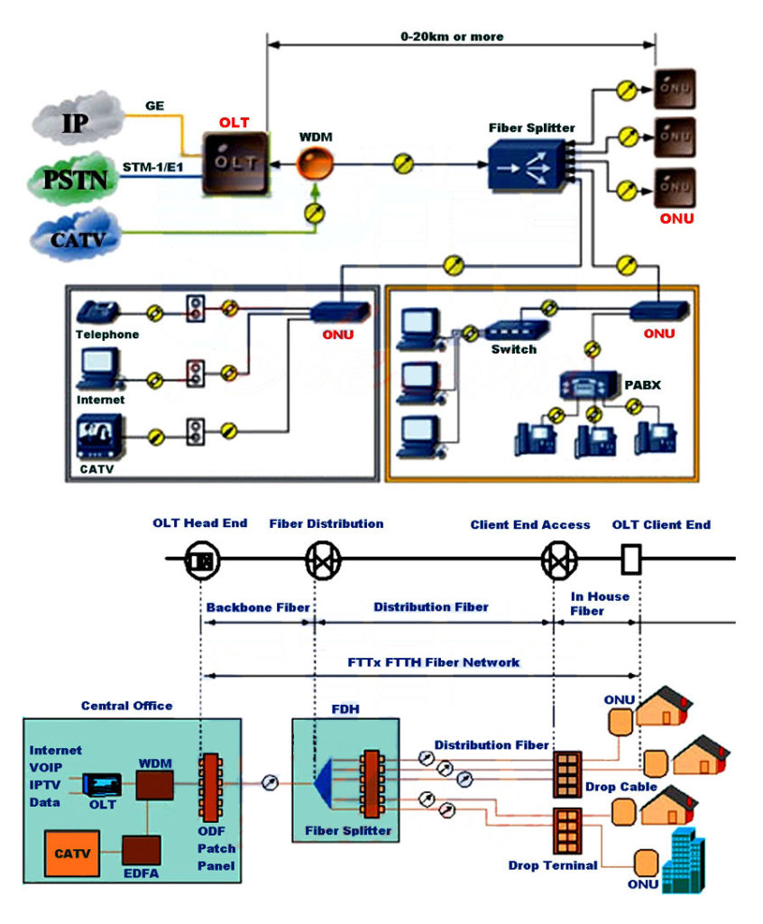
PLC splitter, short for Planar Waveguide Circuit splitter, is used to divide one or two light beams to multiple light beams uniformly or combine multiple light beams to one or two light beams. It is a passive optical device, applied to PON (EPON and GPON in FTTH application) to connect OLT in cerntral office and ONT at the premise. The configuration of PLC Splitter is 1xN (N=2, 4, 8, 16, 32, 64) and 2xN (N=2, 4, 8, 16, 32, 64).
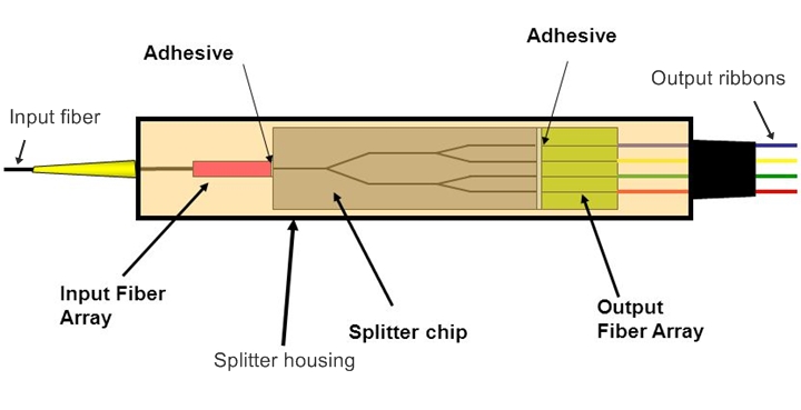
PLC Splitter Fabrication Technology: PLC splitter is based on Semiconductor technology of planar waveguide circuit. PLC splitter consists of one optical PLC Splitter chip and several optical arrays depending on the output ports. The optical arrays are coupled on both end of the PLC splitter chip.
1.2.Common index 1.2.1.Insertion loss insertion loss is the loss of signal power resulting from the insertion of a device in a transmission line or optical fiber and is usually expressed in decibels (dB). The insertion loss of PLC Splitter is: IL=-10lg Pout/Pin. Pout is the optical power of output power, and Pin is the optical power of input power.
1.2.2.Return loss Return loss is the loss of power in the signal returned/reflected by a discontinuity in a transmission line or optical fiber. This discontinuity can be a mismatch with the terminating load or with a device inserted in the line. It is usually expressed as a ratio in decibels (dB). The return loss of PLC Splitter is RL=-10lgPril/Pin. Pril is the optical power, which returns from the device or the system to the input port of PLC Splitter and Pin is the optical power of input power.
1.2.3.Excess loss Excess loss of PLC Splitter is the optical power loss of the total power of all output ports and that of all input ports and is usually expressed in decibels (dB). Excess loss represents the quality of manufacturing technology. The lower it is, the better the manufacturing craft is.
1.2.4.Loss Uniformity Uniformity of insertion loss between ports: the difference value of max. Insertion loss and min. Insertion loss. Uniformity of insertion loss between wavelengths: for the same port, but different wavelengths, the difference value of max. Insertion loss and min. Insertion loss.
1.2.5.Directivity Directivity is the ratio of the optical power launched into an input port to the optical power returning to any other input port.
1.3.Performance parameter Technical parameters with optical connectors in the tender documents from China Telecom in 2012.
Port Configuration
1x2
1x4
1x8
1x16
1x32
1x64
1x128
Fiber Type
G.657A1
Operating Wavelength (nm)
1260nm~1650nm
Max. Insertion Loss (dB)
≤4.1
≤7.4
≤10.5
≤13.8
≤17.1
≤20.4
≤23.8
Loss Uniformity between Ports (dB)
≤0.8
≤0.8
≤0.8
≤1.0
≤1.5
≤2.0
≤2.0
Loss Uniformity between wavelengths (dB)
≤0.8
≤0.8
≤0.8
≤1.0
≤1.0
≤1.0
≤1.2
Return Loss (dB)
≥50
≥50
≥50
≥50
≥50
≥50
≥50
Directivity (dB)
≥55
≥55
≥55
≥55
≥55
≥55
≥55
Port Configuration
2x2
2x4
2x8
2x16
2x32
2x64
2x128
Fiber Type
G.657A1
Operating Wavelength (nm)
1260nm~1650nm
Max. Insertion Loss (dB)
≤4.4
≤7.7
≤10.8
≤14.1
≤17.4
≤20.7
≤24.1
Loss Uniformity between Ports (dB)
≤0.8
≤1.0
≤1.0
≤1.5
≤2.0
≤2.5
≤2.5
Loss Uniformity between wavelengths (dB)
≤0.8
≤0.8
≤0.8
≤1.0
≤1.0
≤1.0
≤1.2
Return Loss (dB)
≥50
≥50
≥50
≥50
≥50
≥50
≥50
Directivity (dB)
≥55
≥55
≥55
≥55
≥55
≥55
≥55
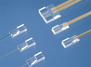
1.4.Classification 1.4.1.Bare Fiber PLC Splitter The package of Bare Fiber PLC Splitter is stainless steel tube. The output fibers can be single fiber of 250um or ribbon fibers of 4 fibers or 8 fibers.
1.4.2.Blockless PLC Splitter The package of Bare Fiber PLC Splitter is stainless steel tube. The output fibers are 900um loose tube. Blockless PLC Splitters are usually installed in Fiber Optic Splice Closure, Optical Distribution Box, Splitter Tray, etc.
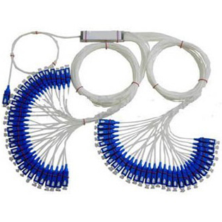
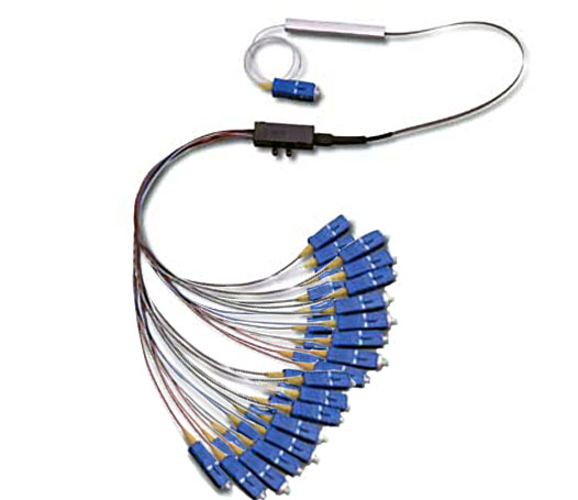
1.4.3.Fanout PLC Splitter The package of Fanout Fiber PLC Splitter is stainless steel tube. The output fibers are ribbon fibers, which connects with ribbon fiber kits and then 900um loose tube. Fanout PLC Splitters are usually installed in Fiber Optic Splice Closure, Optical Distribution Box, Splitter Tray, etc.
1.4.4.Plastic Box PLC Splitter The package of Plastic Box PLC Splitter is a plastic cassette. The output fibers are 2.0mm or 3.0mm cable jacket. Plastic Box PLC Splitters are usually installed in Splitter Tray, Optical Distribution Box, 19 inch rack mounted patch panel, etc.
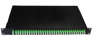
1.4.5.Rack Mount PLC Splitter The package of Rack Mount PLC Splitter is 19 inch rack. Rack Mount PLC Splitters are usually installed in ODF, network rack, cabinet, etc.
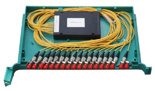
1.4.6.Tray Type PLC Splitter The package of Tray Type PLC Splitter is plastic splitter tray. Tray Type PLC Splitters are usually installed Optical Distribution Cabinet.
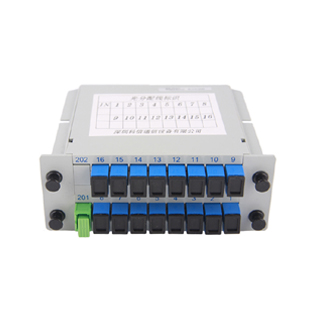
1.4.7.Insertion Module PLC Splitter The package of Insertion Module PLC Splitter is plastic insertion module. Insertion Module PLC Splitters are usually installed Optical Distribution Cabinet, Optical Splitter Box, etc.
Second, Raw Material and Fabrication of PLC Splitter
2.1. Raw material
1
PLC Splitter Chip
Equally split optical power
2
Fiber Array
Couple optical signal
3
Stainless Steel Tube
Package of PLC Splitter
4
Rubber Boot
Protect fiber cable
5
Fiber Optic Connector Parts
Connect fibers
6
Fiber Optic Cable
Protect optical fiber
7
Plastic Box
Package
2.1.1. Main PLC Splitter Wafer Manufacturer Japanese wafer: Furukawa, Hitachi Korean wafer: Wooriro, Corecross, PPI, FIRA Other: COLORCHIP
2.1.2. Main PLC Splitter Chip Manufacturer in China Until 2012, Main PLC Splitter Chip Manufacturer in China are: ACCELINK, SOLOREIN, SHIJIA, HONGHUI, etc.
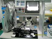
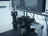
2.1.3. Fiber Array There are two key techniques of fiber arrays: high precision V-groove or U-groove and highly reliable glue. The high precision V-groove or U-groove is made of quartz.
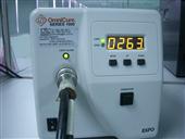
2.1.4. Main glue manufacturer There are UV glue and Fiber Array Assembly glue. Glue Manufacturers of NTT from Japan, DOWCORNING from USA.
Other raw materials:
Item
Material
Manufacturer of Level A
Optical Fiber
Silica glass
Corning, YOFC, Hengtong, Fiberhome, SDGI
Ferrule
High Precision Zirconia (ZrO2)
CHAOZHOU THREE-CIRCLE
Connector Parts
Plastics of PBT and metal
Adapter
Plastic housing of PBT; or metal housing
Sleeve: High Precision Zirconia (ZrO2)
Suzhou TFC, Shenzhen Upcera, Yingfeng, Zhizhuo
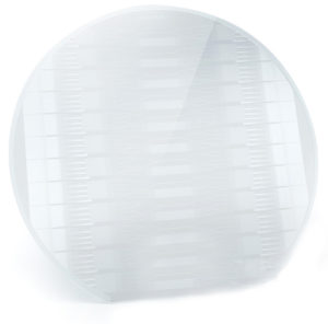
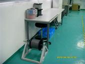
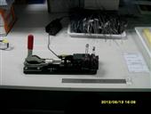
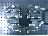
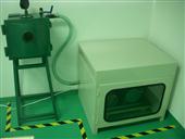
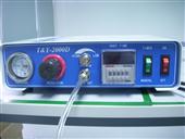
2.2. Fabrication 2.2.1. Wafer Cutting
Wafer cutting
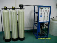
Temperature control of Pure water, to wash and cool during wafer cutting
Compressed air to filter oil contamination and moisture